Saturday, December 3, 2011

The HX Files Xtract 018

Hello and welcome to xtract 018m of the HX Files.
In this issue a 20 watt transmitter with a built in receiver.
This project would be a unit that would be, not to make little of It, a spare transmitter and receiver, and instead of it being left at home, it was to be brought with the main portable transceiver (see photo I below)

Picture 1,
Photo of main rig
just in case anything happened to the main transmitter or receiver. It would be setup as a transmitter, so if needed it could be used straight away. The receiver could be switched on while the TX was on, but as they have their own aerial sockets I could monitor the TX signal without an aerial being connected to the receive socket. There was a plan A or B at the start, I had thought of plan B of making It a transceiver, and by simply adding a coaxial relay, TX/RX switch, a couple of phono sockets and patch leads it could be done, but I wanted to make this spare as a backup transmitter and to keep it as such, so I will carry on and build it as plan A and leave plan B for some time in the future.
The case for this project started life as a 100 watt 2m amplifier, and no, it was not converted to 23cms, it was however converted to junk by its previous owner. I did not ask how he let all the smoke out, but I was told that it was beyond repair, so as the whole amplifier was a large heat sink and would be very handy to have, a deal was done and it was placed into the stores, and there the amp rested for a couple of years awaiting a renaissance. (Wow that was deep, it must be Christmas).
The first thing I done was to remove the old circuit board and switches, (I forgot to take a photo), with that done the original front and rear panels were use to mark out the holes for the new panels, including a new bottom one, but before any cutting out was to be done to the panels I had to place the other parts on the heat sink to give me an idea on were to drill to attach the amp, transmitter and the receiver.


 In photo 2 on the right, you can see the front panel as a blank on the top, and on the bottom with the holes for the various switches, led’s and a couple of carrying handles that would also act as a guard to protect the front. In photo 3 below left, you can see the parts laid out out in their final position with some of the wiring done, the amp top right and the 50mw driver on the left, the receiver is on the bottom right, also seen is some connecting patch leads.


Photo 3


The amp has some pre drilled holes in its own mounting plate and that with the bonding of the amp to the larger heat sink; the amp was finally attached by marking and drilling straight through the heat sink and using some stainless steel nuts and bolts.


Photo 4 on the left shows the back panel with the amp N type socket on the left, you may notice that the two N sockets are different, one been the fitted socket on the amp and the other one a panel mount N to SMA, I was not going to remove the n type fitting from the amp and attach it to the panel via a small lead or adaptor, so not wanting to remove the N type,  a couple of small pieces of the panel was cut out so it would fit around  the sockets, and as I had not got the harder files to work on the steel , I can make a new and better rear panel.


Photo 5 on the left is a picture of the almost finished front panel; the 3 switches are for the 20 watt amp on/off, the receiver, and the DC on/off. The switches and led’s will be marked out by the labelling machine when I find it. The 6 led’s are used for the following, the DC power, amp on/off, TX on/off, RX on/off, the amp has a feature that has a DC monitor voltage that can also be used to indicate if the amp is on so I will use that one as well, and not ruling out a time in the future that the unit could be turned into a transceiver I had a spare led for displaying the relay. In photo 5 the finished front can be seen installed on the heat sink, the keen (Hungary) eye amongst you may have noticed that the led’s seem to white, but when the voltage is applied to them some of them light red and the rest green.
That is all for this Xtract of the HX Files, and indeed for 2011, I would like to thank you for the kind words when I met you at the rallies over the year, so with that, I wish you a very Happy Christmas, and a prosperous, and P45 free 2012.
May all your signals be P5.
73’s
Pat.

Tuesday, November 8, 2011

the HX Files 017

The HX files 017.
Hello and welcome to Xtract 017 of the HX Files.
In this issue.
 Photos, of a 10GHz RX and 23cms TX, operating /p on 1296GHz SSB
 and Goodies from Friedrichshafen.
 Last time in the HX Files.
 I mentioned about building the opposite
 of what was built, (23cms RX and 10GHz TX)
This time it would be 10GHz RX, and 23cms TX. You can see in photo 1 on the left  the setup, with the23cms TX on the  botom right and surprise surprise, the 10 GHz RX on the top left. The 10 GHz RX is a modified LNB, not the normal Sky type but one that is finished in wave guide. The aerials used were the same as the other unit, a slot for 23cms and a Horn type for 10GHz. The unit for the time been would be finished with N type fittings and I would use some adapters like the last time so I could use different types of aerials, I know that using any adapters would cause some power loss but I was not worried by this as I was not making a DX Beacon I was only going to use it from the bottom of my garden which is around 17mts long. The aerial for the 1.2GHz is a dummy load that can be seen in photo 2 below eft.
 I found that this aerial was good enough to do the job of reaching me.  This TX/RX would be easy (ish) to build in the small box like the last one, but unlike it this unit would not be the handy portable or demo unit as the kit would also involve an analogue satellite RX. So the signal would picked up by the RX aerial first and then via the transition to the LNB, and then down to the Sat RX and then back up to the 23cms TX, the cables used would be some coaxial cable from the LNB to the Sat RX, and from the Sat RX the audio and video would be sent up some phono leads to the 23cms TX, and a DC lead for the TX. The marking out and drilling of the box would not be too much of a struggle as the holes I needed were near to the sizes I had drill bits for and would only involve having to do a minimal amount of filing and run the risk of oval holes, I don’t have a large enough reamer for the job but the files would do as long as I took my time as the box was very easy to file and the holes could get bigger all to quick.
 Oops.
I made a chassis template from a cereal box first and then I would  transferred it on to a piece of clear Perspex and then drill out the holes and file the corners for a better fit, but on drilling the second last hole in the Perspex it cracked and snapped in two, and that was followed by words like gosh darn and blast which could be heard coming from the machine shop (the kitchen) I had no more of the Perspex so I used some hardboard instead, but this chassis would only be for testing and would not be a permanent solution as the hardboard would attract moisture and not only fall apart but short out the equipment as I did not use big spacers and if  the chassis did warp it would short out the TX board  and that would not be a good thing. When I was marking out the box I was wondering how to install the LNB, I noticed that at the F connector was at the back of the LNB and that its retaining nut was on the outside, which meant the nut could be used to hold the LNB firmly to the project box and by using the waveguide to SMA adapter and a SMA to N type that was chassis mount would hold the other end and as you may have notice in photo 3 below left, the F and N terminals are close together.
Some UHF Qso’s.
I had a few SSB contacts on 1.2GHz; yes I took some time away from ATV (WHAT!!!) I went /P with Dundalk Amateur Radio Society (EI 7 DAR ) who took part in the VHF/UHF Field day that took place on the weekend of the 2nd  and 3rd  of July. For the 1.2 GHz part of the field day, EI 7 DAR/P was manned by myself and Mark EI 9 FX, and we were using an Icom 910 (2m, 70cms and 23cms), and a 35 element Tonna. Most of the contacts on 23 cms were on the Saturday, and we only heard the same stations again on the Sunday, other members of EI 7 DAR were on 6m,4m and 2meters,  and the 2m crew scored well, they used the callsign EI 0 W/P, anyway enough of that mode.
Friedrichshafen Rally.
The rally was a good one, although the stalls were down the stuff was there, and even if you are a youngster (a pup) or a senior citizen (a grave dodger) you could have bought everything from a microphone to an aerial, and all in-between. At the rally I purchased a few goodies for 23cms and 10 GHz. The biggest was a 60 watt amp for 23cms, and a 2 watt amp to act as a driver for the 60 watt. The QRO amp uses 28 volts+/-, so a 24 volt PSU was also purchased and the one I bought had a adjustment pot fitted to the front, and under test the no load voltage was 27.8 volts and under load (a couple of 12 volt car headlight bulbs in series) dropped this to 27.5 volts and this was well within the amps parameters so I should be getting very close to full power when driven by the 2 watts. I will have to dig deep into the stock piles to look for a suitable project box. I hope to have the unit built soon and have it in the HX files in a couple of issues time if all goes to plan, and the plan is to build it primarily as a base unit, but I could use it /p. even if the main power for the transceiver is 24 volts, I would use an inverter to convert the DC power up to mains voltage, or you could purchase one of the small Lidl/Aldi generators.
That is it for this issue of Echo Ireland, see you next time and may all your reports be P5.
73’s Pat.      

Thursday, July 7, 2011

The HX Files 016.

Hello and welcome to Xtract 16 of the HX Files.
Some brain storming.
During a tea drinking session with Tony (EI 4 DIB) one topic that came up was what to do when you want to test a receiver or a transmitter and there is nobody around to receive a signal from or indeed to send one to.
So not living on top of a mountain I would have no DX stations to lookout for, so the talk came around to a project consisting of a receiver on one band and a transmitter on another. So after more tea (and a visit to the bathroom)
 it was decided that a visit to a couple of my stock locations was called for, to see what parts I had that could be used and would not run the risk of been used for another project.
A Hunting I will go.
After a couple of hours hunting for the parts in my stock stash’s, (shed number 2 and under the bed) and a spot of stocktaking, I decided that a 1.2 GHz receiver and a 10 GHz transmitter would be the frequencies of choice.


 In photo 1 above, with the exceptions of some phono and DC power leads, you can see the parts that would be used in the project. The finished project would be used to receive a 1.2 GHz signal and then that signal would be re-transmitted on 10 GHz. The receiver’s audio and video signal would go direct from the 1.2 GHz to the audio/video inputs of the 10GHz transmitter. The project box used is one of the waterproof ABS type so that I would have piece of mind when or if it ever rained The first thing I done was to do a parts layout in the box to see what would go were, not just the TX and RX, but smaller parts like the cables use for carrying the voltage, audio and video, a DC distribution bar, fuse holders and aerial sockets.  The mounting hardware was bolted through the box and a good quality sealer used to prevent water ingress. A sub chassis was used to secure the various parts so that if I had work on the unit it could be removed easily (ish). So after some measuring and marking (photo 2 below) I cut an opening in one of the side of the box, this opening is the size of the aperture of the solfen head .I would attach the 10GHz on one end of the box and the N type socket on the opposite end of the same size.
 I attached the solfen head to the inside of the box and a small extension piece of waveguide that can be seen in photo 1, with that piece having one flange with threaded holes and the other without the thread . I screwed the unthreaded end to the solfen head and the other end of the extension with the thread would be a lot easier than using small nuts and bolts. I could also quickly attach and remove various aerials for testing and some other fittings, such as a slot aerial, a horn type aerial, even a transition from waveguide to a SMA or N type and most importantly, some attenuators to minimize the RF output, so I would get a better test from a weak signal as what was the point of putting out a QRO signal when QRPP was what I wanted to test the receiver’s, and also, I did not want to “nuke” myself. It would be attached to the fence at the bottom of my garden about 53ft from the shack with some attenuators fitted. If I decided to use this project out and about portable it would not be a big deal to undo it.
Photo 3 below shows the unit before the spaghetti ( the wiring) was added.
 photo 4 below,shows the aerials I would use when the unit was up and running ,the aerial on top is a 23cms slot aerial that is covered with heat shrink, on the bottom left of the picture is a slot aerial and on the right is a horn type aerial both for  10GHz.


Testing, Testing.
Tony’s back garden is 100ft long and it was used for some testing of the finished unit, using a rubber duck type aerial with an adapter for the receiving the 1.2GHz signal and the slot aerial for10 GHz. So using a 1.2 GHZ TX, and a modified LNB and an analogue satellite receiver for 10 GHz receiving, the testing was carried out and all went well,
With all the test carried out and passed, the kettle was put on and the tea drank, later on that night at home I decided to make a mod to the unit, I used 2 long leads, one end of each lead was joined to each of the rx/tx units and those leads were joined by a back to back phono plug joiners. The reason for this was that if I brought it to another ham’s shack the system would be mounted on their mast and with the joiner inside their shack the operator could remove the joiner and connect a camera and then he or she would be transmitting on 10GHz, also by connecting a TV on the other lead you would be receiving 1.2GHz. Not exactly what one would call hi-tech, but it works and it may also get another ham onto the microwave bands and that has to be a good thing.
As a result of the testing of this project I decided to make one the other way around 1.2 GHZ TX and 10 GHz RX. I will have some photos of that next time.
That’s all for this Xtract, and I hope all your signals are P5.
73’s Pat.

Wednesday, April 27, 2011

The HX Files Xcert 015


Hello and welcome to x-tract 15 from the HX-Files.
Firstly
I was delighted to meet and thank the few brave people who came up to me at both the Coolmine rally, and at the I.R.T.S. AGM in Limerick and freely admitted, that they read and enjoyed the HX-Files, so to them again I say thank you.
M E Folan Shield
and winning project.


Kevin Freeney Shield
and winning project


Secondly, I was delighted to be awarded two excellent trophies for construction, the M E Folan shield (EI 6 E), and the Kevin Freeney shield (EI 9 BMB) at the I.R.T.S.AGM in Limerick on the 27th of March. I was, like some of you dear readers a bit reluctant to submit anything but after a bit of prompting I decided to enter a couple of items and was delighted to be awarded the I.R.T.S. shields, so I say to you don’t be shy, your friends will tell you what they think of it, as you can be your own worst judge on your own work, so go on and submit your construction project for the AGM in 2012, you never know what may happen, and don’t forget that the magic word in constructing your project is “prototype”, so it does not have to be ready for mass production, but it has to be safe and tidy, and most importantly it has to do what it says on the tin, so see you at the awards table at the I.R.T.S. AGM next year. 


Next project for/m or /p.
I decided to build a new mast for mobile/portable setup this year. This one would be used mainly for the short sessions when I was only going to setup a station for a couple of hours, and as I have a couple of /p masts a 10m and a 8m one that has yet to see the light of day (and no it is not for sale) that would be used for some of the longer outings and for bigger aerials. I have often been told that you don’t need a huge mast if you are going /p on top of a mountain, so with that in mind this setup would not be a big mast but a small and handy one, if I can use the term “mast” describing an 8ft setup, (that’s 2.44m in new money) this project would involve the mast mounted onto a bracket, and this in turn would be attached onto the tow bar of the car. I did see some types of hardware that could be modified and used for what I needed, but as with most things you need for a /m or /p station you can never get the finished part you need and you would have to adapt and even destroy a brand new item by cutting and wielding it to get it to do what you want it to do. So after a talk with Kevin EI 5 JG, we decided that he would make what I needed from scratch. After trying various sizes of pipe both round and square we ended up with the idea of using a piece of channeling (or a U bar as some call it) and a piece of metal plate. Before the metal plate was wielded to the U piece a 25mm hole was drilled in it, a 15mm hole was drilled in the U piece, and a nut wielded over the drilled hole, and then a piece of round bar was wielded onto the matching bolt giving it a T bar look, and this in turn would act as a permanently attached spanner, a 30cm length of tubing will be used for giving it an extra bit of tension. The reason for the 25mm hole was, as the bolt is been tighten on the other side of the box the ball of the tow bar would be pushed partially into the hole and this would act as extra friction and help with stability.


 Part of the original bracket on the bottom of the mast was wielded to the box and re attached to the mast by its original screws and some large rivets. The top of the mast has some sort of clip on it, this was removed by undoing its retaing screws and a copy of the top was made as this would be used to make a small stub mast that would be attached to an aerial and some matching holes drilled in to line up with the mast top, so it could be attached to the top of the mast. The original top will be placed in the stores shed along with the remaining part of the bottom piece (never to be seen again no doubt). If my car was parked on uneven ground the mast could be tilted vertically by undoing the bolt with one hand and holding onto the mast with the other hand. I would use a small spirit level to give me the vertical line, and if needed I could also use the roof rack on the car and its end clamps to tie some rope to act as stays if the weather conditions were to get a bit windy. I made up a little kit bag to keep with the mast, a disc (on the mast) that goes over the top of the mast and comes to rest at the half way point of the mast and the stays could be attached to that, 2 small pegs, some stay rope, and a persuader. In the pictures you can see the finished mast with the 35el beam for 23cms on the top and under it a 10GHz setup that includes the dish and a 50mw transmitter housed in the box bolted onto it. I hope by the time you read this that the new setup has done a few trials and it may have had some tweaks carried out on it, this seems to be par for the course for home builders.
That’s all for now, see you all next time and may all your reports be P5.
73’s Pat.


Sunday, April 10, 2011

NEW AMP WINS PRESTIGIOUS I.R.T.S. AWARD

My new amp project won one of the I.R.T.S.'s construstion award at their recent AGM in Limerick,which was hosted by the Limerick radio club.
My project was awarded the Folan Shield.
The award gets its name from Professor Enda Folan EI6W, who was President of the Irish Radio Transmitter Society from 1958 to 1960,  EI 6 W presented this shield to the Society.  It is awarded for home constructed equipment built to the highest standard and a technical write-up including the specification of the item is required.  The shield was first presented in 1959 to T.J. McCrossan EI7A.
In the pictures below you will see the award and the amp.


I was also awarded the Kevin Freeny Trophy
The Fingal and North Dublin Radio Clubs donated this trophy to the Society in memory of the late Kevin Freeny EI9BMB.  The trophy is awarded for proficiency in equipment construction.  It was first awarded in 1988 to Dave Redmond EI2GB.
Below is some pictures of this award and project.
73's
Pat EI 2 HX.


Thursday, March 3, 2011

New Amp 006, Finished at last.

Hello and welcome to the final part of the "new amp" project ?.
Sorry for in the delay in posting the final part of the new amp.
Since the last update to the Blog, the transceiver has been up and running for a couple of weeks.
As I mensioned in a previous Blog Post, I had left the rig running for up to half an hour at times and in some cases a full hour,the unit would never be transmitting for such a long period in real life, but it is good to know that your project is up for the job.
These trials would show up any faults weither in the design or soldering,and at home on the test bench not on a hill miles away. The RF power was put into a dummy load with the fans running on the rig,the heatsink was warm at most after the hour. It was hot hot hot after 20 minutes with no fans running but still less than the manufactures maximum recomended temperature,thanks to the large heat simk.
Strange as it may sound, I also brought it with me in the car even when it was not compleat just to see how it held together and if any parts would vibrate,as I would be using it /m as well as /p when it was finished. I needed to know the build quality and that the  project would not shake apart.


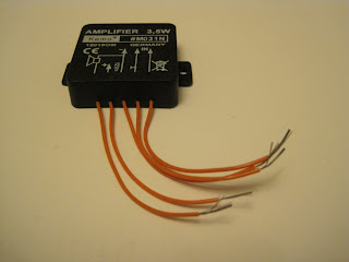
In photo1on the left,you can see a small audio amplifier,this was needed as the output from the monitor was very low and no sound could be heard from the speaker I installed in the front of the unit.There was plenty of audio when I used some headphones, but this would not be ideal if Iwas
                              giving a demo with the unit.


23cms preamps
 

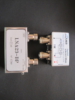
In photo2 on the left, you can see a couple of  Preamps (35db on left an 30db on right) one of these will help with the rx when I install it later.
As you can see there is a differents in the size of the preamps, and indeed the same can be said about the coaxal relays that can be seen in photo 3 below,and in photo 4 below that.

N type relays


SMA relays


When it is been installed I will also be replacing the relay for a 4/5 pole type.With this relay I will be able to bypass the preamp and use it when required.As I said this will be done when the unit has a few hours of work done as /p and at QTHR.
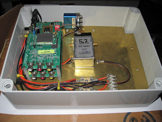
In the photos you can see the new parts to be installed. I dont know what to do when it comes to trying to hide the connecting dc cables and coaxal cables.Who knows what amp mk2 will be like,maybe I will install a sub chasis made of a non conductive material, pcb board,or a plastic chopping board would be a good choice, and they are available in various sizes.
Below you can see some other pictures,the images on the monitors are.The top one shows an image of
EI 4 DIB/P on HF at the Skerries Mills on the Air in 2010.
Bottom image is part of the /P station of Derek EI 7 CHB also at the Mills on the Air weekend.
73' from Pat EI 2 HX.


Saturday, February 26, 2011

The HX Files 014

Hello and welcome to epessiode 14 of the HXfiles.
 I hope you all had a quite and uneventful Christmas, and I would like to wish you all a very happy and a peaceful new year, and that all you buy at the forthcoming rallies works.
You can never have enough.
 As usual I have made the same New Year resolutions, not to buy anything I have 2 or 3 of, but with the first rally of 2011, (Coolmines) only days away , (Rally date 20th-2nd 2011).
I found some space for a project box or two just in case I see any must haves at the rally, as over Christmas I did yet another stock take and found stuff I did not know I even had, so I won’t have to buy  too much at the rallies this year as all my stock bins are full. You would think that with the dozens of different sizes of patch leads that you have, you would have years of stock to keep yourself supplied for all your projects, but after the project in the last issue, and its latest modification I used quite a few leads of around the same size and with the coaxial relay, and the now installed pre amp, I found out that a lot of leads the same size is not a bad thing after all.      
7 GHz
This project in this issue is of a 7 GHz transceiver. All the parts were collected over a period of a couple of years. I bought the7 GHz horn aerials about 3 years ago with the intension of removing their flanges and grafting on a smaller 10GHz horn aerial to convert them to 10 GHz and then I would have a good aerial setup for 10 GHz. (as I Hadn’t got any Tx or Rx equipment for 7 GHz yet) But at the next rally I was at, I saw and bought a couple of 10 GHz aerials, and the 7GHz ones went into stock. The aerials were aloud to acquire some protective coating, (dust).A year later I came across a couple of transitions that would convert the flange at the end of the aerial to a N type socket, and they would give me some leeway with the aerials and the connections on the Tx/Rx units as I did not know what connections would be used, but at least I had some more parts, but as yet, no Tx or Rx units. After some more of the protective coatings had been laid down on the aerials and transitions (about 8 months worth) I came across some Tx/Rx units several rallies later, and I also purchased a 50mw amp.


The Tx and Rx boards came with a small panel aerial each (photo 1 on the right). I did a couple of test with the small panel aerial that came with them, and the horn aerials.
But for this test I would use the larger panel aerial.
Photo 2 below.
shows the front and back of them.(Yes I have two of them) The tests I did involved leaving the RX board and the horn aerial on a 20ft (6m) pole, then using some dc and audio video cables connected to the video recorder. I had made sure everything was working before I left my home and that I was receiving a signal. So, with the equipment pointing to a nearby hill, off I went. This would not be guest work as I had done a few experiments like this before; the location I was using was a piece of land beside the QTH of the late Dermot (EI-2-AK). I would have loved to have been able to be doing the receiving and watching the signal as I drove along the route to the hill, but that would have been highly dangerous, and just a tad against our licencing conditions about operating an unattended station. So of I went with the Tx signal blasting out the mega watts
 (photo 3 below, shows the Tx/Rx without cables)) and with the Rx connected to the video recorder at home, recording my signal as I drove along the route to the top of the hill.
The TX now has a power out put of 50mw, and the unit including the panel aerial was connected to the roof rack via cable ties (what would we and the police do without them).There is no picture of this as it was not a pretty sight, I would make a proper bracket later, I used a camcorder mounted on the dashboard at first.


 Later on, I switched to the camera mounted on the towing eye of the car see photo 4 left. I would have a good idea looking back at the recording to see what the signals were like, how wide or narrow, and also how they would differ from the horizontal and vertical planes.


Alone all alone
 The RX and TX units have only 4 frequencies to play with, but this should not be too much of a problem as the band is a little quiet at the moment, both of signals and operators.so I had to send a signal to myself ,(that’s not the first time I have talked to myself and maybe not the last) I decided to place the parts in the one box and make it into a transceiver and terminated it with an N type socket; the end of the horn aerial is finished in waveguide so I connected an N type to wave guide transition. This was not as easy as it sounds because the holes in the mounting flange on the aerial did not match the holes in the flange on the transition. After a talk with Michael (EI-5-GG) it was decided to make a plastic adaptor to hold the aerial and transition together and inline, while they were been marked for drilling, (the adaptor would be removed before final attachment) This was a tedious job cutting and filling to get a tight fit so the flanges both line up and be drilled correctly. With that job done (a couple of hours later) the next job was to decide how to attach the transceiver to the aerial and then to a pole.

Photo number 5 on the left shows the finished plate with all the gear attached. A couple of brackets were made to hold the transceiver to the plate rather than to bolt it direct to it as I only had the one TX unit at the moment, so I could go portable, as well as operate from the home. Another tricky job was the coaxial fly leads that were fitted to the boards; they had the SMA connectors the wrong way around (for me that is).I had a choice to change the lead or the relay, using the relay I have would mean using adapters, I had to decided what to do, to change the fly lead and to try and put a sma chassis socket on the board, or failing that a sma plug on a fly lead, or go with plan “A” and use the adaptors .So plan “A” it was. The adaptors would do as a short term solution as I would be only doing a few tests, and if I did not get a relay sooner rather than later I will have to get the soldering iron out and replace the fly leads. Installing the parts wasn’t too bad as the Tx/Rx boards were the same size and I decided to place one above the other using some small plastic spacers. It’s always a problem what to with all the connecting wires, whether to hide them or to leave them in view but tightly bound together so they look neat and tidy, It is nice to see but If you have to modify or replace parts you can find yourself making a new wiring loom, if you have put a chassis board in the box you can place the loose wires underneath and leave yourself with some room for manoeuvre if the worse happens. 
That’s all folks.
That’s it for another issue.
 Once again a happy New Year and I hope all your signals will be P5.
73’s de Pat.